Senior Design Project @ USC
Collaborators: Eduardo Cardenas, Natalie Maciel, Raul Torres Jr.
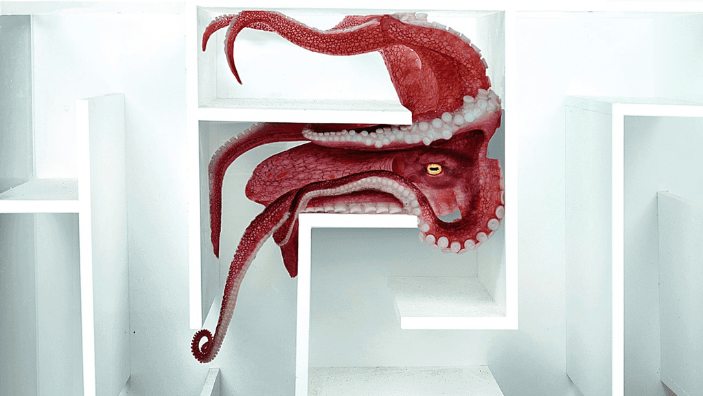
The Problem
Current advancements do not allow sensor cuffs to be placed around aquatic animals that change shape (like cephalopods), making data collection from these species difficult.
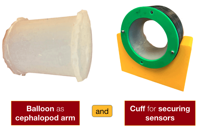
Project Goal
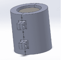
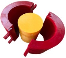
Exterior Structure
A solid cylinder and two symmetric cylindrical halves that enclose the solid cylinder. The outer cylindrical halves have extrusions with holes for inserting screws to bind the mold into a tight, cohesive piece that would also allow for removing the manufactured silicone part.
Interior Structure
The solid cylinder sits flush with the bottom of the outer cylindrical pieces to make a solid bottom surface so that when Ecoflex is poured, none leaks out of the bottom.
Considerations
This mold design considered maintaining equal thickness, easily removing the part from the mold, and reducing material waste due to leaks from lack of stability.
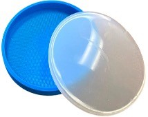
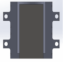
Top Cap
The previously made open-face cylinder is placed open-face into the end cap mold, filled with Ecoflex 00-30, and sits until cured. Once cured, the hollow cylinder is achieved.
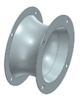
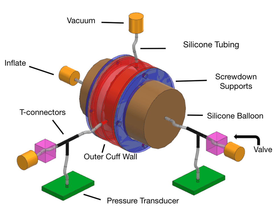
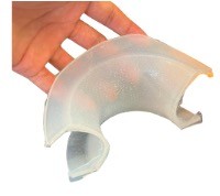
Inner Wall Geometry (Grey)
The purpose of the inner wall of the cuff was to be the flexible side that could expand to make contact and secure the balloon. To perform this action with minimal buckling, the main section of the wall was designed to be a curved surface
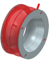
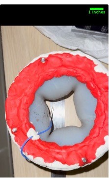
Cuff Outer Wall (Red)
The cuff was designed to be self-sealing, where the inner wall of the cuff acts as a gasket, sitting between the rigid outer wall and a pair of screw-down supports.
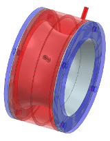
Supports (Blue)
The flexible inner wall, rigid outer wall, and screw-down supports create the cuff structure used in this experiment.
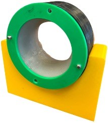
Full Assembly
Full 3D printed and molded assembly
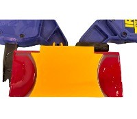
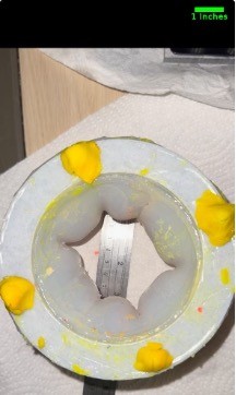
Ecoflex in Mold
Inner (yellow) and outer (red) mold pieces allow ecoflex to harden into the correct shape. These molds were designed in SolidWorks and 3D printed.
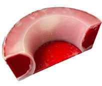
Inner Piece Removed
The result of the mold is half of the inner wall.
Inner Wall Half
Ecoflex wall separated from it's mold
Full Inner Wall
Two halves joined together with Ecoflex
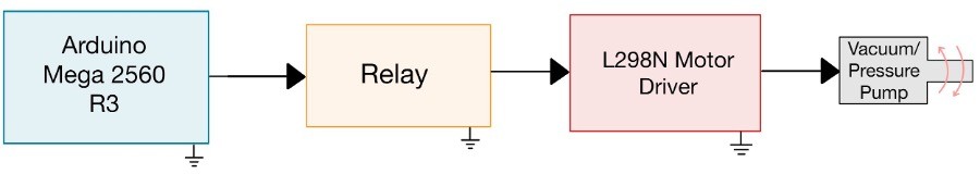
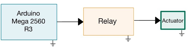
Actuator Code Logic
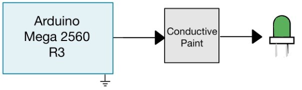
The logic around which the motor can act on the body revolves around controlling the actuator position. The wiring logic states that when an actuator is in the “off” position, the pressurizing pump has access to the body and will inflate the body when the motor is turned on.
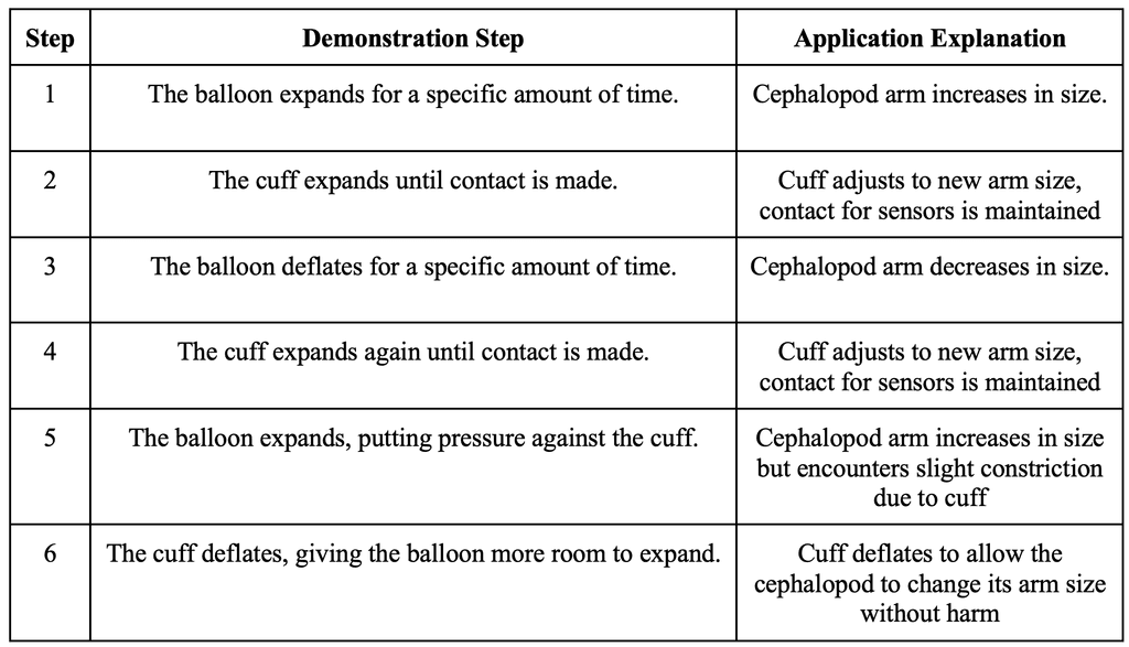
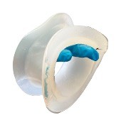
Balloon and Cuff Contact
During data collection, it was observed that under no contact, the capacitive values fluctuate but stay under a value of 25 (the units of this value are unknown; however, the units are not crucial to any logic within the code). When the value from the conductive paint circuit breaches this threshold of 25, it is determined in the code that contact is made.
Balloon Expanding Past Cuff?
If all three of the following conditions are met, this means logically that the balloon is trying to expand past what the cuff is allowing it to expand at that time, which is the signal to deflate the cuff:
1. Is there contact between the cuff and balloon?
2. Is the pressure inside the cuff increasing more than three times in a row?
3. Is the pressure inside the cuff greater than an experimental found average pressure value of 1.3 psi?
Thick Ecoflex Internal Wall
Thin Ecoflex Internal Wall
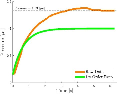
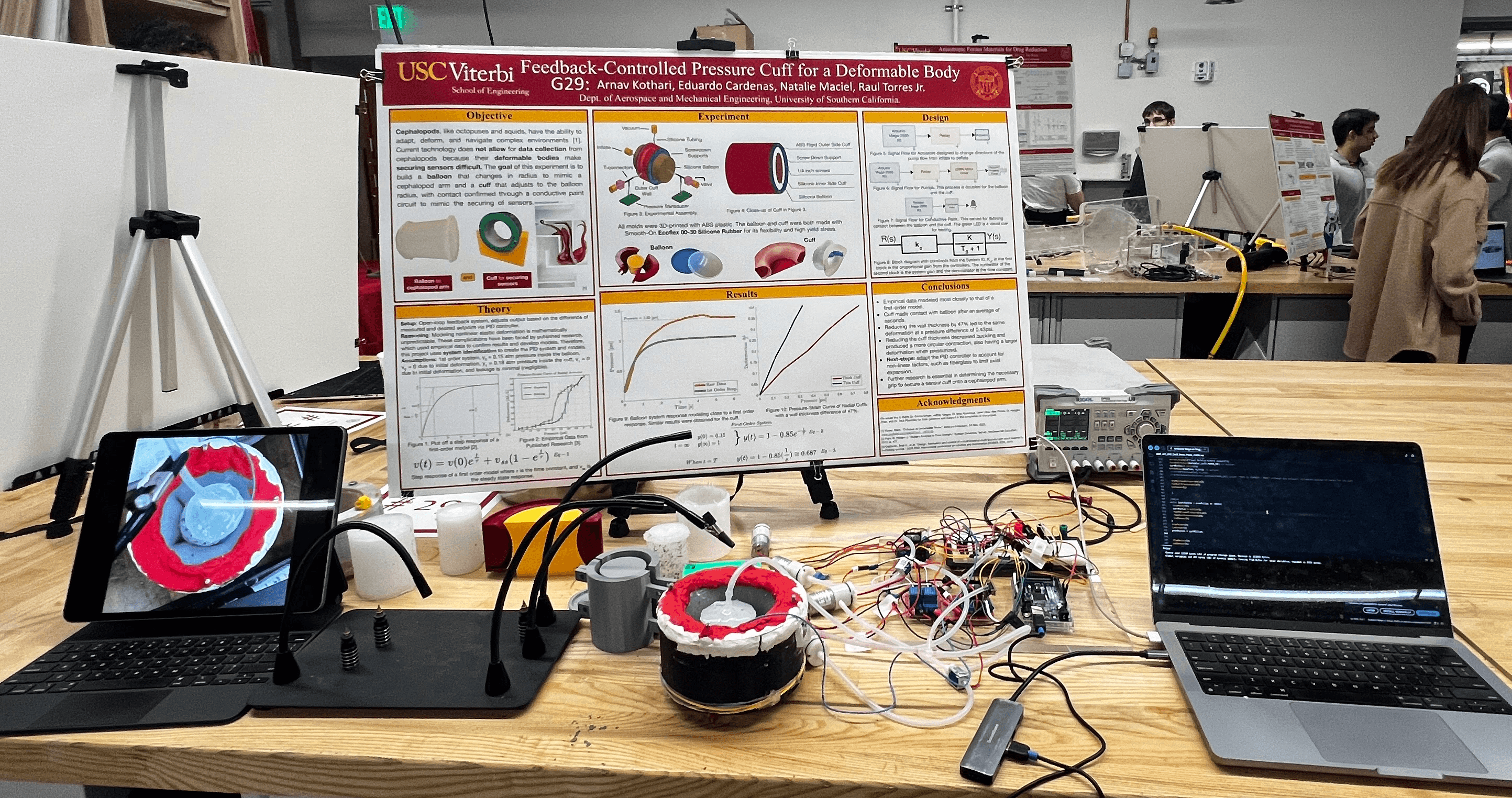
1st Order Response
Inflation data of the balloon resembled the 1st order model for a step response. An overshoot of of approximately MP = 2% was desired to have as little deviation from the desired pressure as possible. Based on several iterations of inflating and deflating the cuff and balloon, it took approximately 4.5 to 5 seconds for the inflation of both the balloon and cuff to risk over-pressurizing the balloon or cuff. Therefore, a settling time of 5 seconds was set as a design requirement for the PID controller.
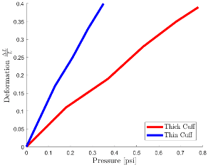
Pressure Strain Curve of Cuff Inflation
The“thick” cuff had a wall thickness of 0.13in, and the “thin” cuff had a thickness of 0.08in. This 47% thickness reduction led to a 0.43psi difference at the same deformation.
The thinner cuff was also observed to have a more circular contraction. This is again due to the reduced stiffness and resistance to stretching. This flexibility enables the cuff to contract uniformly and adopt a more circular cross-section, the most energy-efficient shape for resisting internal pressure.